Bose 9 Pin Connector Diagram

Bose Lifestyle Wiring Diagram 10 Msd 65 Wiring Diagram Begeboy Wiring Diagram Source

Infiniti G35 Amplifier Wiring Diagram Top Wiring Diagram Gallery Cycle Singer Cycle Singer Aiellopresidente It
Wiring Diagrams For The Z32 300zx Audio Stereo System
Bose Cable Pinouts Ecoustics Com
Need B6 Non Bose Rear Amp Pinout Audiworld Forums

Diagram Bose Lifestyle 28 Wiring Diagram Full Version Hd Quality Wiring Diagram Aglowengineersmail Hotelagriturismovacanze It
This is the headset connector that I needed for my Bose 0 headset It came with instructions to install it into a system with existing GA panel jacks I would like to see a diagram on how to install the connector alone, without GA jacks, as I plan to do.
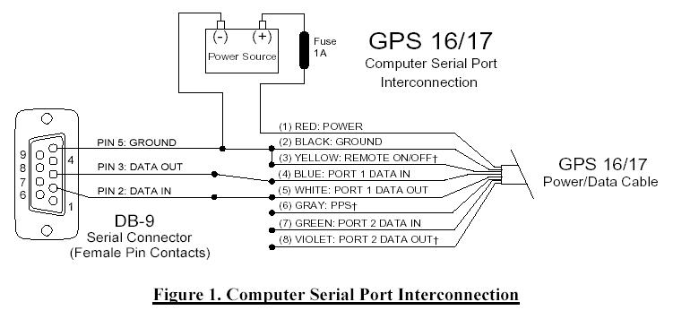
Bose 9 pin connector diagram. Unfortunately Bose seems to have used quite a variety of ports/plugs, cables Sketch out a diagram of the required hookups Then go online and look for the matching plug pinouts May take some time and effort but that is what will be needed to get everything connected and working properly. Amphenol 9 Position Pin (Male) Receptacles 9 Circular MIL Spec Connector are available at Mouser Electronics Mouser offers inventory, pricing, & datasheets for Amphenol 9 Position Pin (Male) Receptacles 9 Circular MIL Spec Connector. Mobile Information Labs is available to assist you with specific Delco car stereo diagrams of all types and with is easy to follow and understand diagrams.
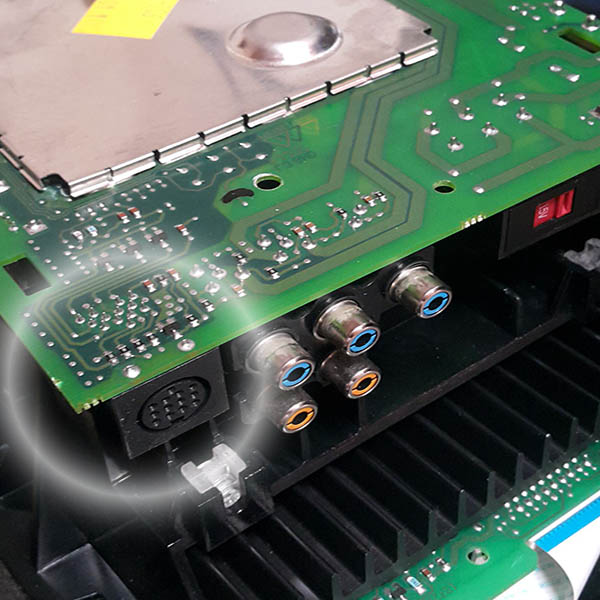
C5 Bose CD or cassette upgrade wiring notes Bose CD/Cassette Stereo System Info The C5 Bose stereo system is based on a modified Delco head unit The \”Delco/Bose\” head unit, CD or casssette, has four connectors called C1, C2, C3 and C4 on the rear panel C1/C2, which is a single siamese connector, is used for all Delco head units, not. Collection of bose amp wiring diagram A wiring diagram is a streamlined traditional photographic representation of an electrical circuit It shows the parts of the circuit as streamlined forms, as well as the power and signal connections between the tools. The prior owner had a really crappy repairjob on the inputcable (the 8pin DINcable) I cant understand how he have connected this?.
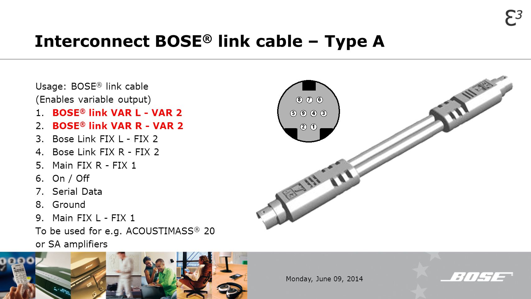
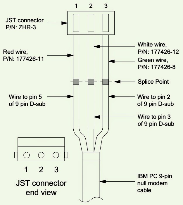
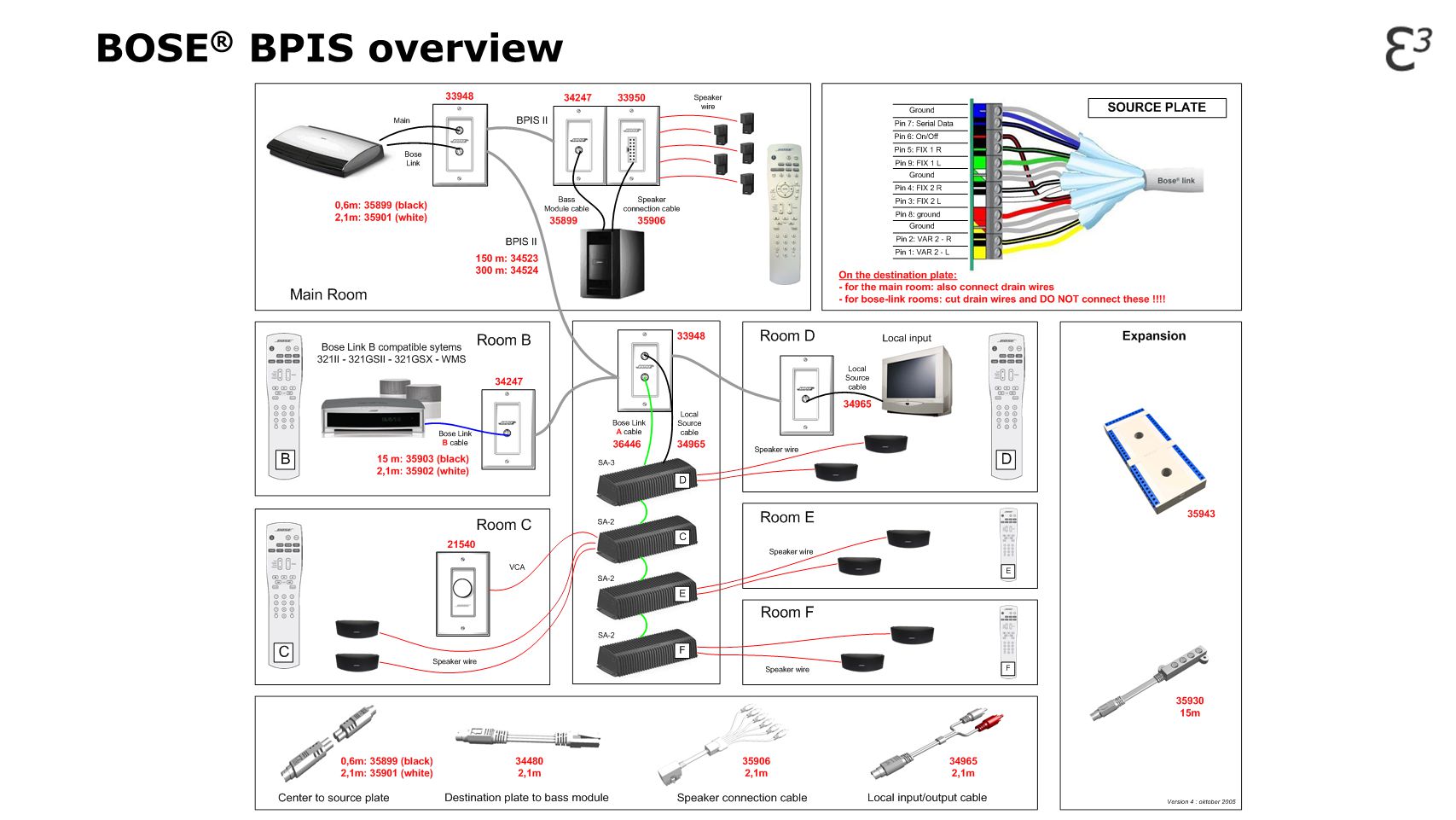
Note that the diagrams represent the “port” side of the connections, ie the connector on top of the meter and the physical DB9 serial port on the back of the computer The cable ends will be mirror images of the diagram Eight Pin MiniDIN Connector PinOuts If your Alicat Instrument was ordered with the standard eight. Cables Each cable uses circular 9pin connectors on either end The difference between the two types is in how they are wired “A” cables contain 9 wires that correspond to each of the 9 pins on the connector Here is a detail of what each pin carries Bose Link A Cables 1 Variable Stream 2 Left 2 Variable Stream 2 Right 3 Fixed Stream. Every Mercedes stereo wiring diagram contains information from other Mercedes owners Mercedes Radio Stereo Wiring Diagrams Read More ».
Questions & Answers for Bose 9 pin din wiring diagram understood could u be more descriptive or post a photograph bose powered acoustimass 9 speakerEasily connect preinstalled speaker wiring (up to 14 gauge) to a Bose Lifestyle home theater or Acoustimass system of results for "wiring bose speakers" Cyber Acoustics CAFFP Speaker Sound. Pin 9 is power to the screen, and pin 15 is screen ground 14 output to the screen The you have 2 smaller connectors is the big connector Pin 5 are output to the screen (light control) Mic are on pin 3 and 9 The last wire on the pin 9 on the second connector I do not know what for You do not have ACC or any steering control inputs to the. Connector C ARINC 429 Pinout Diagram The ARINC 429 connector, or Connector C, plugs into a 9pin female Dsub receptacle located on the back of the HXr display unit underneath Connector A and Connector B A male 9pin Dsub connector, along with eight male pins and a backshell, are included with the display unit.
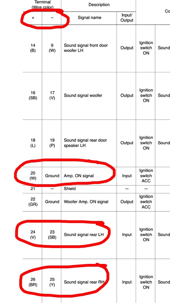
General Aviation Headset Wiring Schematic 95 Honda Diagram Headlights Usb Cable Tukune Jeanjaures37 Fr bluetooth headset user manual bose wireless aviation plug wiring diagram converting to 6 pin connector headphone install kit general a auto on diy pilots of america standard jack steinair inc pac aircraft audio frequently sao diagrams full x community schematics. Caution The signal ordering is not identical for all Bose amplifiers amps with pigtail third wire = audio out fourth wire = 12 VDC 1368 amps with 6 pin connector third pin = 12 VDC fourth pin = audio out The LGND signal is a signal ground, it is not a power supply ground connection It is a common. The Bose aircraft panel connector cannot be installed to an audio system using transformercoupled audio outputs Call the Bose Aviation Headset Department for details Connecting power directly to pins 5 or 6 will result in damage to the microphone.
C5 Bose CD or cassette upgrade wiring notes Bose CD/Cassette Stereo System Info The C5 Bose stereo system is based on a modified Delco head unit The \”Delco/Bose\” head unit, CD or casssette, has four connectors called C1, C2, C3 and C4 on the rear panel C1/C2, which is a single siamese connector, is used for all Delco head units, not. I cover a similar example here (System #3 in the diagram) Wiring 2 or 3way speakers in series causes issues with the sound Using resistors will work fine, but you’ll lose 1/2 power across them;. Yes if they all match 3 through 9 not occupied matches the beige connector Pin 14 has Brown/violet wire which means you have a UQA radio Never drive faster than your guardian angel can fly!!!.
AllenBradley PLC Serial Cable with a 9pin femaletomale gender changer Modicon Modbus cable Siemens SIMATIC 505 Programmable Controller Serial Cable with a 9pin femaletomale gender changer You can build an RS232 cable using the diagram above, except the gender of the RMCend connector should be reversed. If you researched the Bose Web site you would find that the 15 pin connector that you need to connect your bass module to the speaker connections on your receiver is feet long with ( ) bare wire on the ends The Bose rep should have told you this. Unfortunately Bose seems to have used quite a variety of ports/plugs, cables Sketch out a diagram of the required hookups Then go online and look for the matching plug pinouts May take some time and effort but that is what will be needed to get everything connected and working properly.
Collection of d sub 9 pin connector wiring diagram A wiring diagram is a streamlined conventional photographic representation of an electric circuit It reveals the parts of the circuit as streamlined shapes, as well as the power and also signal links between the gadgets. While researching the Bose audio system wiring in our cars, I came across a number of helpful posts/threads on this forum However, the information was generally scattered across multiple posts in multiple threads, and I was never able to find complete pinout diagrams for all three Bose amplifier connectors. Assortment of bose amp wiring diagram A wiring diagram is a simplified standard pictorial depiction of an electrical circuit It shows the components of the circuit as simplified shapes, and also the power as well as signal connections in between the devices.
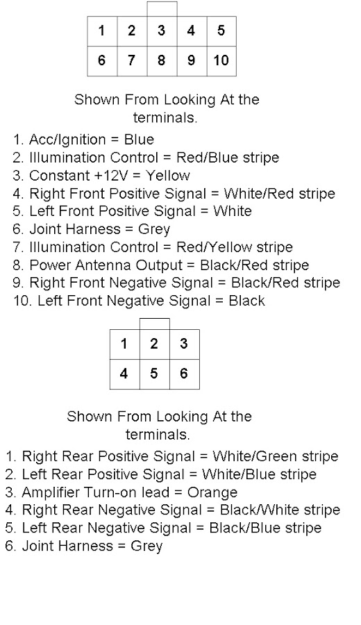
Pinout of Car Audio ISO connectorISO is a standard connector that is used in the radio unit (head unit) There are contacts for the power supply off / on (controlled by the ignition key), the speakers and automatic antenna. If your headset is aircraftpowered, a 6pin connector must be installed and mounted to an aircraft panel See “Mounting the aircraft panel connector” on page 31 Note An adapter is available from Bose to convert a 6pin connector to a dual G/A plug for additional connection flexibility To connect the headset 1. SoundTouch 130 44 out of 5 stars 191 $1395 $ 13 95.
Need pinouts for miniDIN 9pin (Bose Link) to RJ45 cable AND pinouts for miniDIN 9pin Bose Link to RCA plug Bose Acoustimass Professional Service Manual Free download as PDF File pdf), Text File txt) or read online for free Bose Acoustimass 16 speaker system Manual Bose Mk2 Service Manual. 11 Mazda CX9 CX9 Radio Audio Bose Wiring Schematic Diagram Colors Install April 5, 16 CarAudioWiringDiagram Leave a comment Here is the stereo radio wiring information for your 11 Mazda CX9 CX9 body with the standard or Bose amplified systems. Wiring Diagram, SmartLight2 Wiring Schematic, SmartLight2 Control Plug Pin Functions 13 Pin Harness 15 Dodge Only Installation Manual 13 Pin Harness Ford F250F550 Upfitter Harness Installation Manual.
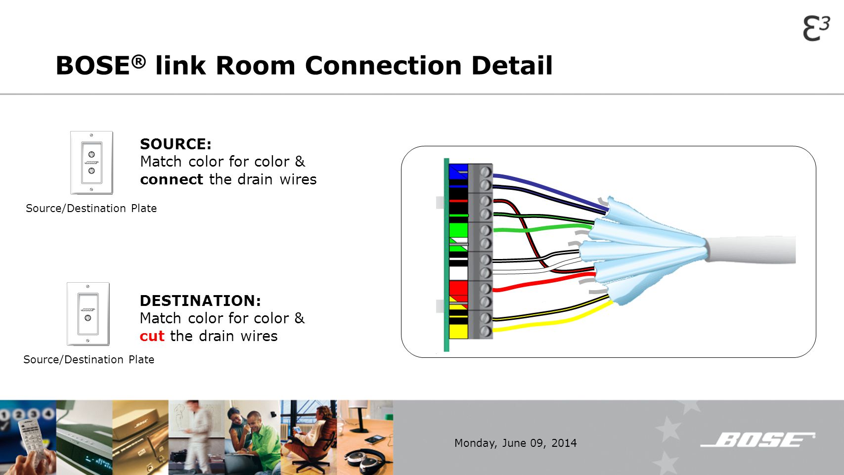
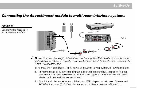
7 Pin Connector Wiring Diagram – 7 pin ag connector wiring diagram, 7 pin connector wiring diagram, 7 pin connector wiring schematic, Every electric arrangement is made up of various different parts Each component should be set and connected with other parts in specific way If not, the arrangement won’t work as it should be. The Bose® link AL8 Homewide Wireless Audio Link also works with some products that are not Bose linkcompatible The RCA connectors are colorcoded, red for right and white for left 1 Insert the adapter cable DIN connector into the Bose® link jack on the transmitter (INPUT) or receiver (OUTPUT) jack, as appropriate 2. Having a Mercedes stereo wiring diagram makes installing a car radio easy Find the Mercedes radio wiring diagram you need to install your car stereo and save time Scroll down and find the Mercedes wire guide you need It’s that easy!.
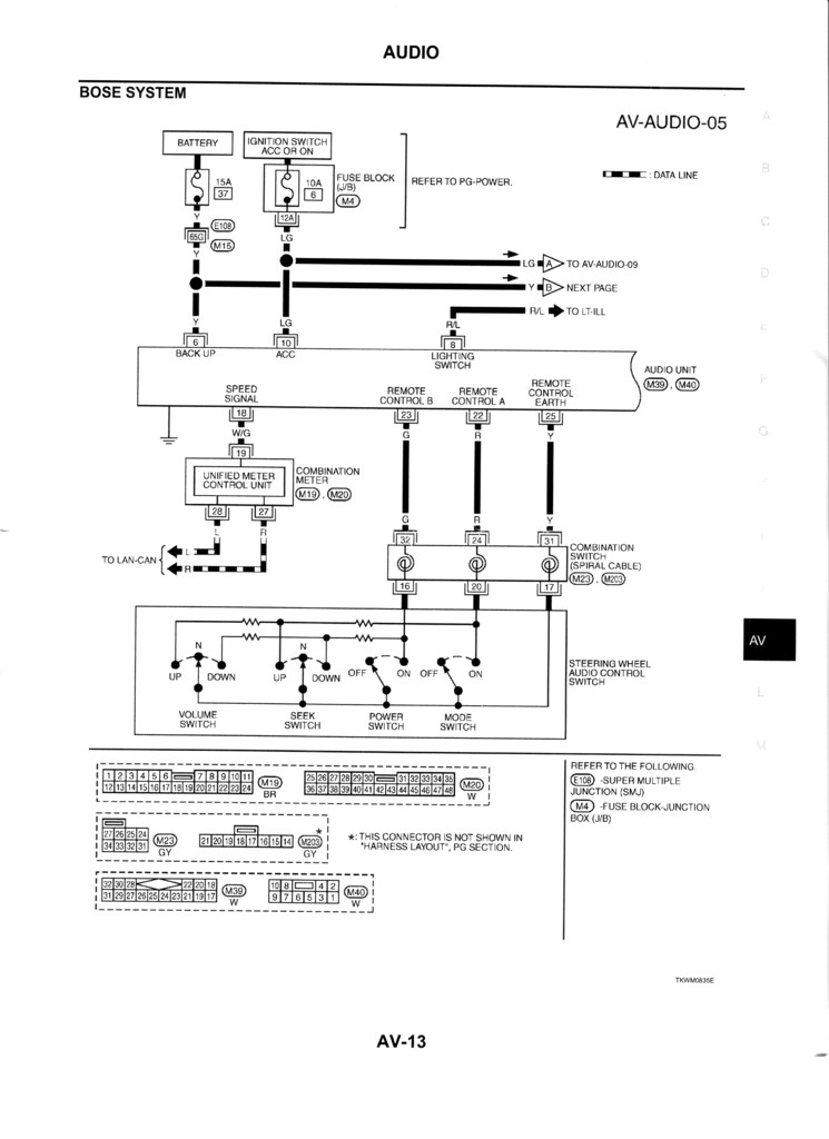
While researching the Bose audio system wiring in our cars, I came across a number of helpful posts/threads on this forum However, the information was generally scattered across multiple posts in multiple threads, and I was never able to find complete pinout diagrams for all three Bose amplifier connectors. BOSE Wiring Diagram Discussion in 'FX (0308) Electronics & Lighting' started by toy4x, Feb 26, 09 Feb 26, 09 #1 toy4x Premium Member Premium Messages 2,375 Likes Received 36 Location Hesperia, CA Car 04 FX35 Name Andrew Garages 1 Here is the BOSE wiring diagram for the FX35/FX45 This makes it a heck of a lot easier to wire in. This custom panel connector and attached wiring harness is for use with the installed control module of the Bose Aviation Headset X, Bose 0, Lightspeed Zulu Panel Powered, David Clark OneX Panel Power or any other panel powered aviation headset that uses a 6pin Redel / LEMO Connector Semipermanent installation provides aircraft power and audio to headset.
Delco Stereo Wiring Diagrams Are you tired and frustrated because your Delco car stereo is giving you fits as you try to install or remove the car stereo?. Assortment of bose amp wiring diagram A wiring diagram is a simplified standard pictorial depiction of an electrical circuit It shows the components of the circuit as simplified shapes, and also the power as well as signal connections in between the devices. Bose acoustimass 5 series ii wiring diagram – A Novice s Overview to Circuit Diagrams A first appearance at a circuit representation might be complicated, but if you could check out a train map, you can review schematics.
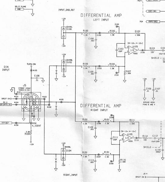
Microsoft Word 13pin Wiring Schematicdoc Author chrjod Created Date 8/27/04 PM. The prior owner had a really crappy repairjob on the inputcable (the 8pin DINcable) I cant understand how he have connected this?. Plug one end of the HDMI™ cable into an HDMI INPUT connector on your TV If an HDMI cable is already connected to an HDMI input on your TV, you can use this one Just disconnect the other end 3 Page 6 YSTEM ETUP Audio OUT 4 Plug one end of the audio input cable into the connector on the control console.
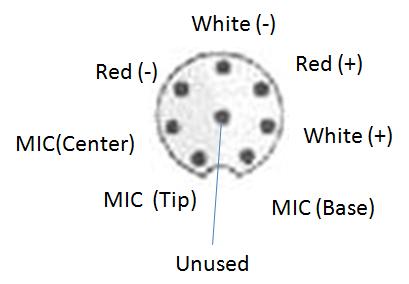
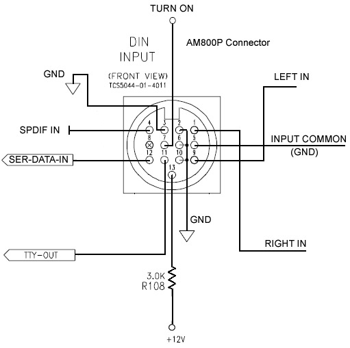
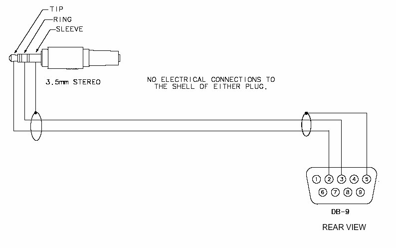
BOSE Wiring Diagram Discussion in 'FX (0308) Electronics & Lighting' started by toy4x, Feb 26, 09 Feb 26, 09 #1 toy4x Premium Member Premium Messages 2,375 Likes Received 36 Location Hesperia, CA Car 04 FX35 Name Andrew Garages 1 Here is the BOSE wiring diagram for the FX35/FX45 This makes it a heck of a lot easier to wire in. It seems that top of 3,5mm is connected to pin 7 mid of the 3,5mm is connected to pin 3 base of the 35mm is connected to pin 6 ground on the rcas is pin 5 and pin 2 Tip of rcas is pin 4 and pin 1. 15 pin DB connector for Acoustimass and bare tined wires and RCA plug to go to receiver Bose Acoustimass 6/10 series (5) Speaker Cables RCA to Bare Wire ’ White Cord $ Bose Acoustimass 16 speaker system Manual Bose Mk2 Service Manual Refer to the wiring diagram on page Remove the eight screws (8) that secure the woofer (1) to the cabinet.
Bose acoustimass 5 series ii wiring diagram – A Novice s Overview to Circuit Diagrams A first appearance at a circuit representation might be complicated, but if you could check out a train map, you can review schematics. But that’s a compromise made when wiring speakers up where that’s not normally possible. Found an old Bose Lifestyle 18 DVD headunit, a PS18 (LSPS) amplified subwoofer AND an Acoustimass 10 passive sub but have no cables Need pinouts for miniDIN 9pin (Bose Link) to RJ45 cable AND pinouts for miniDIN 9pin Bose Link to RCA plug.
1 Could you please discuss the different types of connectors on aftermarket radios I've seen several different types a "ISO" which is a pair of 8pin connectors, and b A single pin connector (two rows of ten pins) c A single 16pin Kenwood connector and probably others 2. I have a Logitech X230 subwoofer with 2 satellite speakers, one of which has a power switch and volume control These satellite speakers attach to the passive subwoofer via a 9'pin D connector What i am trying to achieve is to connect the subwoofer to my mini HiFi system's single Subwoofer RCA. There is one gray 24 pin connector and one 8 way ,on the amp They are C1 and C2 The pins in each connector are labled with a letter for the row location ( A or B) and a number for a pin location in that row Example A10 C1 Pin location is in connector C1row A pin 10 Here is a connector view or c 1 and c 2.
Feb 09, · Found an old Bose Lifestyle 18 DVD headunit, a PS18 (LSPS) amplified subwoofer AND an Acoustimass 10 passive sub but have no cables Need pinouts for miniDIN 9pin (Bose Link) to RJ45 cable AND pinouts for miniDIN 9pin Bose Link to RCA plug Jun 10, · Find great deals on eBay for bose acoustimass subwoofer wiring. 09 Mazda CX9 CX9 Radio Audio Bose Wiring Schematic Diagram Colors Install If you find any conflicting info please leave a comment with what you found in your Mazda CX9 If you don’t see the audio radio wiring diagram you need comment and we will try to add it ASAP Thanks for looking!. The Bose® link AL8 Homewide Wireless Audio Link also works with some products that are not Bose linkcompatible The RCA connectors are colorcoded, red for right and white for left 1 Insert the adapter cable DIN connector into the Bose® link jack on the transmitter (INPUT) or receiver (OUTPUT) jack, as appropriate 2.
Caution The signal ordering is not identical for all Bose amplifiers amps with pigtail third wire = audio out fourth wire = 12 VDC 1368 amps with 6 pin connector third pin = 12 VDC fourth pin = audio out The LGND signal is a signal ground, it is not a power supply ground connection It is a common. Collection of bose amp wiring diagram A wiring diagram is a streamlined traditional photographic representation of an electrical circuit It shows the parts of the circuit as streamlined forms, as well as the power and signal connections between the tools. Serial and Parallel cable schematics and wiring diagrams Home Page Use the I/O ActiveX control for serial and parallel communication ASCII Code Table 9 PIN to 9 PIN Serial Cable 25 PIN to 9 PIN Serial Cable Parallel Printer Connector Db25 DB25 PIN (Female) SIGNAL DB25 MALE CONN DB25 FEMALE CONN 1 > STROBE *.
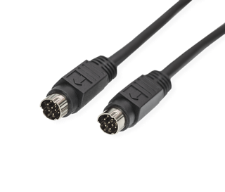
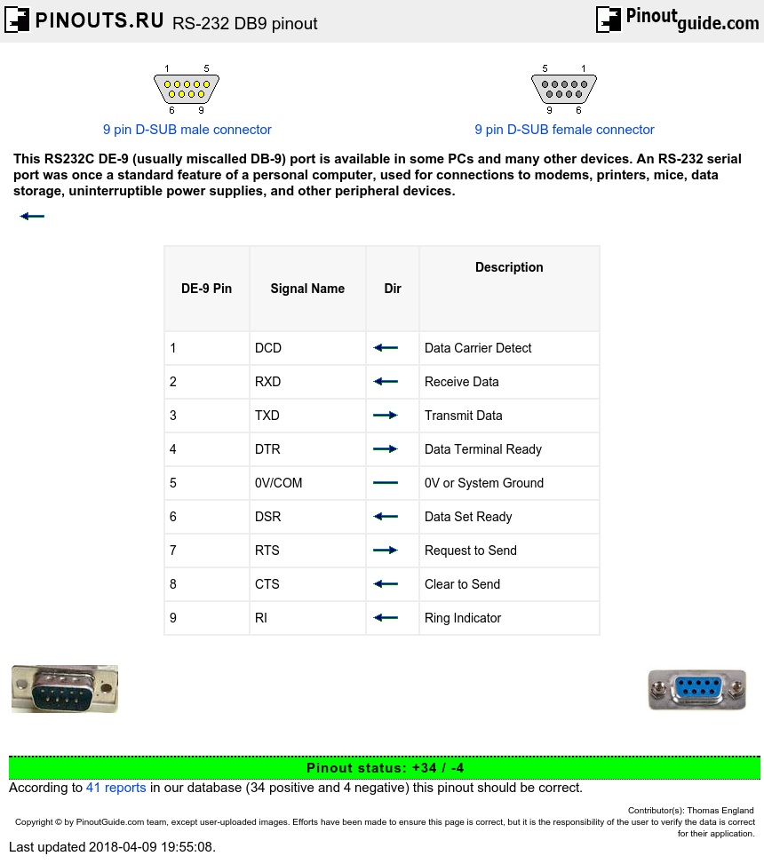
HQRP 9pin Male to 9pin Male (M/M) Audio Input Cable Compatible with Bose Replacement Lifestyle 135 235 48 T10 V ;. Pin 9 is power to the screen, and pin 15 is screen ground 14 output to the screen The you have 2 smaller connectors is the big connector Pin 5 are output to the screen (light control) Mic are on pin 3 and 9 The last wire on the pin 9 on the second connector I do not know what for You do not have ACC or any steering control inputs to the. Named for the shape of their shell, Dsubminiature connectors are a classic standard in the computing world There are four very common varieties of this connector DA15, DB25, DE15, and DE9 The pin number indicates the number of connections provided, and the letter combination indicates the size of the shell.
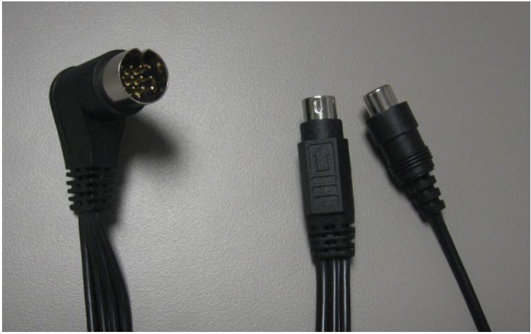
15 pin DB connector for Acoustimass and bare tined wires and RCA plug to go to receiver Bose Acoustimass 6/10 series (5) Speaker Cables RCA to Bare Wire ’ White Cord $ Bose Acoustimass 16 speaker system Manual Bose Mk2 Service Manual Refer to the wiring diagram on page Remove the eight screws (8) that secure the woofer (1) to the cabinet. Assortment of bose amp wiring diagram A wiring diagram is a simplified standard pictorial depiction of an electrical circuit It shows the components of the circuit as simplified shapes, and also the power as well as signal connections in between the devices. The issue is that on the speaker end, the wire has a proprietary Bose connector that can't be plugged into a "normal" speaker And on the other end, there's an RCAtype connector, which also won't.
Bose Cable Pinouts Ecoustics Com
Bose Link Music Throughout Your Home Ppt Video Online Download
Bose Acoustimass 9 Din Ecoustics Com

Bose Car Amplifier Wiring Diagram Bookingritzcarlton Info Car Amplifier Amplifier Bose

Re Av48 And Compatable Acoustimass Bose Community

8 Pin Satellite Radio Connector Diagram Wiring Schematic Electrical Transformer Diagram For Wiring Diagram Schematics
Http Www Myuremote Com Bose Link Pdf

Re Av48 And Compatable Acoustimass Bose Community

Amazon Com Bose Lifestyle Cable 9 Pin Mini Din 15 Ft Male Male For Bose Only Home Audio Theater

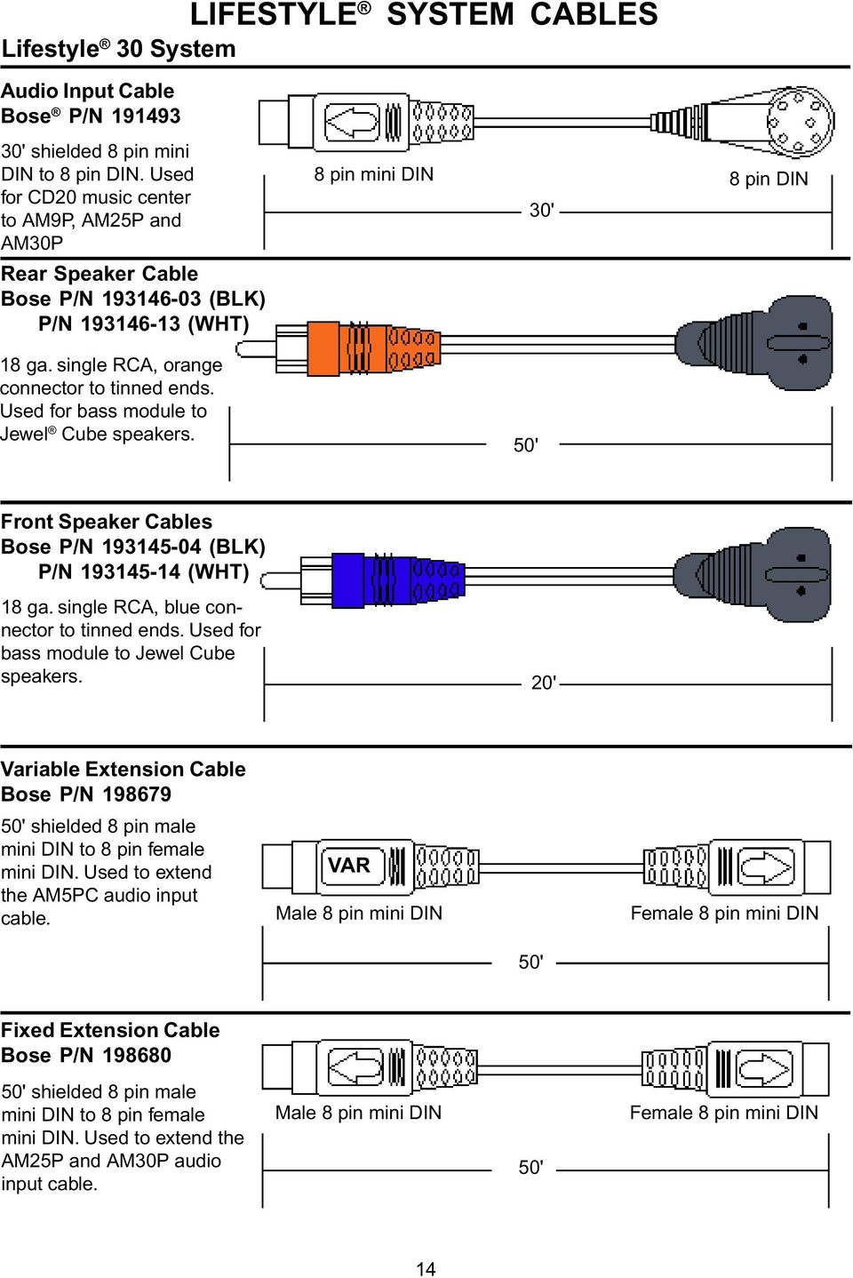
Lifestyle System Cables Pdf Free Download

Solved How To Make A 15 Pin Female Sound In Cable Fixya

30 Harman Kardon Hk395 Wiring Diagram Free Wiring Diagram Source
Adding A Subwoofer To Your G37 Sedan W Bose Myg37
Bose Lifestyle Wiring Diagram 10 Msd 65 Wiring Diagram Begeboy Wiring Diagram Source

Wiring Diagram For 9 Pin Trailer Connector 19 Ford Festiva Ignition Wiring Diagram Bege Wiring Diagram

Bose Car Amplifier Wiring Diagram Bookingritzcarlton Info Car Amplifier Bose Amplifier

Bose Dvd Player Wiring Diagram Seniorsclub It White White Seniorsclub It

Bose Car Amplifier Wiring Diagram Http Bookingritzcarlton Info Bose Car Amplifier Wiring Diagram Audio Design Car Amplifier Speaker Wire

Db9 Pinout Bose Wiring Diagram 3 Way Circuit Wiring Diagram Bege Wiring Diagram
Audio Input Cable Male 9 Pin Mini Din To Male 9 Pin Mini Din Bose Support
Bose Lifestyle 5 Service Manual Manualzz
13 15 Cx 5 Bose Wiring Diagram What To Tap To Avoid Bose Processing Mazdas247

Solved I Have A Bose Acoustimass Fixya

Bose Tv Wiring Diagrams 12 Volt Battery Wire Harness Jeep Wrangler Yenpancane Jeanjaures37 Fr
Audio Bose Centerpoint Surround System Part 2 2 9 3 10 Saab Workshop Information System Online

Amazon Com 25ft Media Center To Subwoofer Link Cable For Select Bose Lifestyle 18 28 38 35 48 System 8 Pin Mini Din To Rj45 Interface Home Audio Theater

14 18 Mazda 3 Mazda 6 W Bose Full System Breakdown Analysis 04 To Mazda 3 Forum And Mazdaspeed 3 Forums
Db9 Pinout Bose Wiring Diagram 3 Way Circuit Wiring Diagram Bege Wiring Diagram

Lifestyle System Cables Pdf Free Download
Master Electronics Repair Bose 3 2 1 How To Change Region Code Bose 3 2 1 Bose Wave Radio Troubleshooting

Setting Up Your System
Bose Wiring Diagrams Saab 9 7x Wiring Diagram Bathroom Vents Yenpancane Jeanjaures37 Fr
Bose 102 System Cable For Lifestyle 8pin Rj45 Black 9 00 Meter
Q Tbn And9gcq7gwbqv1gpcoi 3p2tojcmpqfuuhvhsmy6k028xu Usqp Cau

Db9 Pinout Bose Wiring Diagram 3 Way Circuit Wiring Diagram Bege Wiring Diagram
Audizine Forums

Audizine Forums

Lifestyle 50 And Its Acoustimass 30 Series Ii Be U Bose Community 199
Bose Link Music Throughout Your Home Ppt Video Online Download
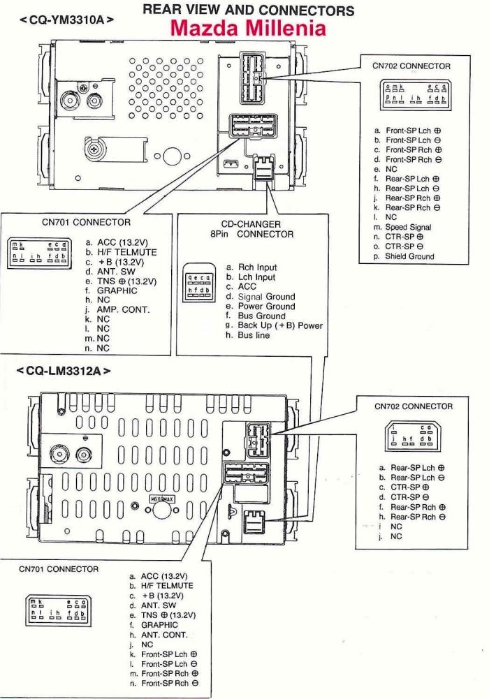
Mazda Car Radio Stereo Audio Wiring Diagram Autoradio Connector Wire Installation Schematic Schema Esquema De Conexiones Stecker Konektor Connecteur Cable Shema

Bose Cinemate Wiring Diagram Gm Coolant Temp Sensor Wiring For Wiring Diagram Schematics
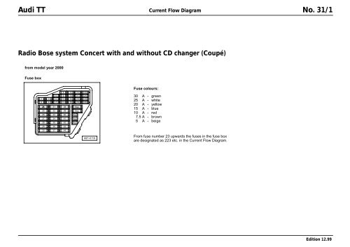
Audi Tt Coupe Bose Concert Wiring Diagram Pdf
9 Pin Din Connector Wiring Diagram Klipsch Promedia Ultra 5 1 Thx Stratocaster Wiring Diagram Series Bege Wiring Diagram

5 1 Bose Lifestyle 12 Series Ii Subwoofer Full Accessories Power Cable Adapter Foc 15pin Rca Cable For Media Center No Speakers Pls Do Read Full Info Absolutely Non Nego Anymore Fast Deal 99 99nett Drop Frm 129 99 Electronics
Is There A Way To Hook This Pic1 To This Pic 2 Avs Forum
Bose Lifestyle 18 Wiring Diagram Best Fusebox And Wiring Diagram Power Stable Power Stable Contentflowservice It
Bose Link Music Throughout Your Home Ppt Video Online Download
Archive Through July 06 08 How To Diy Repair A Bose Lifestyle 12 Subwoofer Ecoustics Com

18 Stunning Bose Car Amplifier Wiring Diagram Ideas Bacamajalah Electrical Wiring Diagram Car Stereo Diagram

10 Mazda Cx9 Bose Amp Input Wiring Carav

Mark S Hangout Mark S Hangout Blog
Lifestyle 50 And Its Acoustimass 30 Series Ii Be U Bose Community 199
Bose Link Music Throughout Your Home Ppt Video Online Download

06 A6 C6 Mmi Bose Amp Power Questions Audiforums Com

Diagram Bose Acoustimass 5 Wiring Diagram Full Version Hd Quality Wiring Diagram 1azigbeediagram Soluzionevacanza It
Bose Cable Pinouts Ecoustics Com
Bose Ps321 Subwoofer Rewiring For Another System Audioholics Home Theater Forums

Bose Lifestyle 12 Wiring Diagram Kawasaki Bayou 2 Wiring Harness Rainbowvacum Tukune Jeanjaures37 Fr
Wireless Bluetooth Headset User Manual Manual Bose

Bose Lifestyle Av18 Bose Community

Audio Cable Lifestyle Bose Community

Diagram Bose Din Cable Wiring Diagram Full Version Hd Quality Wiring Diagram Diagramza Cooking4all It
Db9 Pinout Bose Wiring Diagram 3 Way Circuit Wiring Diagram Bege Wiring Diagram
Q Tbn And9gcrpl3thjzgnk3mtolkeohxawwji5fieeoymjtcrgri59kbna1m4 Usqp Cau

Bose Link Rca To 9 Pin Din Adapter Cable 2853 07 Ebay
Rs232 Wiring

13 Pin Breakout Box Schematic 4 Download Scientific Diagram
Bose Wiring Diagram Gt From Elearn Alfa Romeo Forum
Control Bose With Ipad Iphone Android
Q Tbn And9gcq7gwbqv1gpcoi 3p2tojcmpqfuuhvhsmy6k028xu Usqp Cau
Assets Bose Com Content Dam Bose Dam Web Pro Global Products Loudspeakers Designmax Dm5c Downloads Tds Designmax Dm5c En Pdf

Mark S Hangout Mark S Hangout Blog

Bose Lifestyle 28 Wiring Diagram Wiring Diagram For A 1986 540 Ford Tractor Oonboard Yenpancane Jeanjaures37 Fr

Diagram 4 Pin Wiring Diagram Audio Full Version Hd Quality Diagram Audio Baguadiagram Summitacquanetwork It
Q Tbn And9gcr0b0c4zmsn L4pn9phxb4zl9o Oqugjeoigfi3nyqbath0 Ibi Usqp Cau
Http Is asikooli Ee Bose Din Cable Wiring Diagram Pdf

Solved I Need The Pinouts For The Bose Cinemate Series Ii Speaker Fixya

Unique Audi Bose Amp Wiring Diagram Diagram Diagramtemplate Diagramsample Car Amplifier Diagram Electrical Wiring Diagram

Bose Lifestyle 18 Wiring Diagram Best Fusebox And Wiring Diagram Power Stable Power Stable Contentflowservice It
Wireless Bluetooth Headset User Manual Manual Bose

Bose 321 Service Manual Pdf Document

Bose Lifestyle Wiring Diagram 10 Msd 65 Wiring Diagram Begeboy Wiring Diagram Source

Bose Link Cable Wiring Diagram C280 Fuse Diagram Begeboy Wiring Diagram Source

Nissan Bose Stereo Wiring Diagram Wiring Diagram Overview Circuit Garlic Circuit Garlic Nuovaresinmontaggi It

12 Mazda 3 W Bose Amp Wiring 04 To Mazda 3 Forum And Mazdaspeed 3 Forums

Bose 9 Pin Din Wiring Diagram Fixya

Help With Bose Companion 3 Mini Din 9 Pin Audiophile

Help Making A Bose Fix Cable Avforums
Db9 Pinout Bose Wiring Diagram Data Jack Wiring Pontiacs Tukune Jeanjaures37 Fr
Need Wiring Diagram For 9 Pin Bose Speaker Plug Page 1 Home Cinema Hi Fi Pistonheads Uk
Lifestyle System Cables Pdf Free Download
Audizine Forums
Bose Amp Wiring Diagram Chevy Wiring Diagram Electron Option Electron Option Bellesserepoint It
Audi 04 08 Symphony Ii Concert Ii Head Units Pinout Diagram Pinoutguide Com

Audi Tt Coupe Bose Concert Wiring Diagram Pdf Audi Tt Coupe Bose Concert Wiring Diagram Pdf Audi Tt Audi Bose

Amazon Com 12ft Media Center To Subwoofer Link Cable For Select Bose Lifestyle Av18 Av28 Av38 Av48 Ps28 Ps48 Ps38 Mc1 Etc System 8 Pin Mini Din To Rj45 Interface Home Audio

Solved I Have A Bose Acoustimass Fixya

Lifestyle 50 Multi Room Interface Connectors Bose Community


